Single Leg Motors
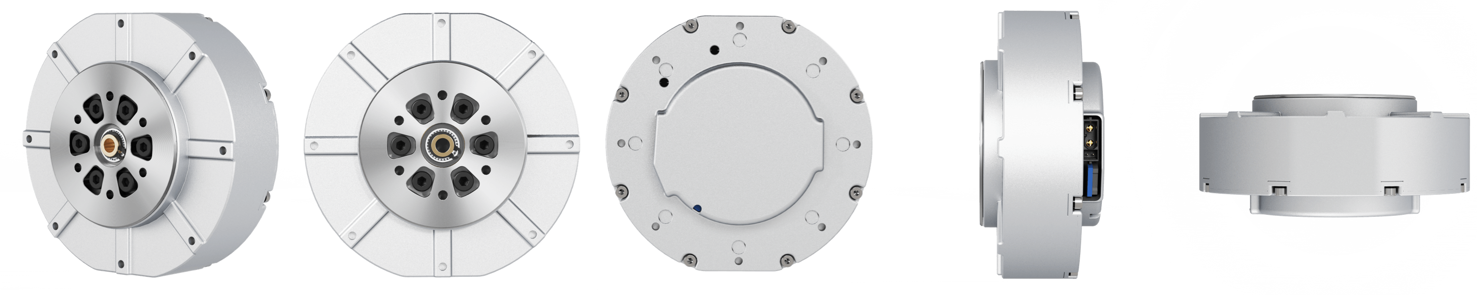
#Robotics #Single_Leg_Project #Motors The motors used for the single leg robot are Go-M8010-6 motors.
Why PMSM motors?
In the early days of robotic, the motors used were stepper motors. These motors control their angles, so they will follow any desired angle. The problem with these motors is that if enough pressure and force is exerted on them, they will turn and get out of position, losing track of their angle. These motors were also the reason the early robots their signature robot-like movements.
(#todo: reliable reference for this needs to be added)
Today, Permanent Magnet Synchronous Motors (PMSMs) are used for robotic purposes. Imagine a permanent magnet. When this magnet is placed in a magnetic field, it starts rotating and rotates until it is aligned with the magnetic field. A familiar example of this is a compass whose magnetic dial turns until it is facing the magnetic North pole of the Earth.
Now what happens if the magnetic field starts rotating itself? Then, the permanent magnet will start rotating as well to stay aligned with the magnetic field. This is the basis of motors. They have a rotating part, appropriately named the rotor, which is a permanent magnet. The non-rotating part is called the stator. A rotating magnetic field is created in the stator by applying sinusoid currents with different phases to the stator. Thus, the rotor rotates in the motor.
The output torque of the motors is also related to the phase difference between the rotor and the stator and can be controlled.
To save users from dealing with 3-phase voltages and currents, many motors already implement a very low-level controller, called Field-Oriented Control (FOC). Note that we still have one single degree of freedom, meaning we cannot have a desired angle or angular velocity and a desired torque. What we have control over is the torque that the motor applies, which is computed as
\[\tau = \tau_{ff} + K_p (q_{des} - q) + K_d (\dot{q}_{des} - \dot{q}),\]where $q$ and $\dot{q}$ are the angle and angular velocity of the motor, $q_{des}$ and $\dot{q}{des}$ are the desired angle and angular velocity and $K_p$ and $K_d$ are position and velocity gains. You can note that this is exactly a PD controller with a feed-forward torque. We do not have any further control on the low-level control of the motor. At each timestep five values should be sent to the motor, which are $\tau{ff}$, $q_{des}$, $\dot{q}_{des}$, $K_p$ and $K_d$. Based on the inputs, the motor will be in one of the following modes:
- Position Mode: In this mode, only $K_p$ and $q_{des}$ are specified. The other three parameters are set to zero. In this mode, the motor goes to the given angle.
- Speed Mode: In this mode, only $K_d$ and $\dot{q}_{des}$ are non-zero. The motor keeps rotating at a constant speed.
- Damping Mode: In this mode, only $K_d$ is non-zero. This is a special speed mode, where the desired speed is zero. This means that the motor generates a torque to resist moving, even in the presence of external torques.
- Torque Mode: Only $\tau_{ff}$ is non-zero. The motor outputs the given torque.
- Zero Toque Mode: Everything is set to zero. This mode is a special torque mode where the desired torque is zero. Note that this is different than a motor that is off, because in this mode, the motors tries to cancel the friction torques present at the motor; therefore, if rotated by hand, it will rotate noticeably smoother compared to when the motor is off.
- Force Position Mixed Mode: All parameters have values. This might be useful for example, when we’re trying to compensate for gravity or friction with the feed-forward torque and at the same time, we want to follow a desired angle or angular velocity profile.